Introducing a powerful stabilized 12 V power supply. It is built on the LM7812 stabilizer chip and TIP2955 transistors, which provides a current of up to 30 A. Each transistor can provide a current of up to 5 A, respectively, 6 transistors will provide a current of up to 30 A. You can change the number of transistors and get desired current value. The microcircuit delivers a current of about 800 mA.
A 1 A fuse is installed at its output to protect against large transient currents. It is necessary to ensure good heat dissipation from transistors and microcircuits. When the current through the load is large, the power dissipated by each transistor also increases, so that excess heat can cause the transistor to breakdown.
In this case, a very large heatsink or fan will be required for cooling. 100 ohm resistors are used for stability and to prevent saturation as the gain factors have some variation in the same type of transistors. Bridge diodes are rated at least 100 A.
Notes
The most expensive element of the whole structure is perhaps the input transformer. Instead, it is possible to use two car batteries connected in series. The voltage at the input of the regulator must be a few volts higher than the required output (12V) so that it can maintain a stable output. If a transformer is used, then the diodes must be able to handle a sufficiently large forward current peak, typically 100A or more.
No more than 1 A will pass through the LM 7812, the rest is provided by transistors. Since the circuit is designed for loads up to 30A, six transistors are connected in parallel. The power dissipated by each of them is 1/6 of the total load, but it is still necessary to ensure sufficient heat dissipation. Maximum load current will result in maximum dissipation, requiring a large heatsink.
To effectively remove heat from the heatsink, it may be a good idea to use a fan or water-cooled heatsink. If the power supply is loaded to its maximum load, and the power transistors are out of order, then all the current will pass through the microcircuit, which will lead to a disastrous result. To prevent breakdown of the microcircuit, there is a 1 A fuse at its output. The 400 MΩ load is only for testing and is not included in the final circuit.
Computing
This diagram is an excellent demonstration of Kirchhoff's laws. The sum of currents entering the node must be equal to the sum of the currents leaving this node, and the sum of the voltage drops on all branches of any closed circuit of the circuit must be equal to zero. In our circuit, the input voltage is 24 volts, of which 4V drops at R7 and 20 V at the input of LM 7812, i.e. 24 -4 -20 \u003d 0. At the output, the total load current is 30A, the regulator supplies 0.866A and 4.855A each 6 transistors: 30 = 6 * 4.855 + 0.866.
The base current is about 138mA per transistor, to get a collector current of about 4.86A the DC gain for each transistor must be at least 35.
TIP2955 meets these requirements. The voltage drop across R7 = 100 ohms at maximum load will be 4V. The power dissipated on it is calculated by the formula P = (4 * 4) / 100, i.e. 0.16 W. It is desirable that this resistor be 0.5 W.
The input current of the microcircuit is supplied through a resistor in the emitter circuit and the B-E junction of the transistors. Let's apply Kirchhoff's laws again. The input current of the regulator consists of 871 mA current flowing through the base circuit and 40.3 mA through R = 100 ohms.
871.18 \u003d 40.3 + 830. 88. The input current of the stabilizer must always be greater than the output. We can see that it only draws about 5 mA and practically should not heat up.

Testing and errors
During the first test, it is not necessary to connect the load. First, we measure the output voltage with a voltmeter, it should be 12 volts, or not a very different value. Then we connect a resistance of about 100 ohms, 3 watts as a load. The voltmeter reading should not change. If you do not see 12 V, then, after turning off the power, you should check the correct installation and soldering quality.
One of the readers received 35 V at the output, instead of the stabilized 12 V. This was caused by a short circuit of the power transistor. If there is a short circuit of any of the transistors, you will have to unsolder all 6 to check the collector-emitter junctions with a multimeter.
Somehow recently, on the Internet, I came across one circuit of a very simple power supply with the ability to adjust the voltage. It was possible to regulate the voltage from 1 Volt to 36 Volts, depending on the output voltage on the secondary winding of the transformer.
Take a close look at the LM317T in the circuit itself! The third leg (3) of the microcircuit clings to the capacitor C1, that is, the third leg is the INPUT, and the second leg (2) clings to the capacitor C2 and a 200 Ohm resistor and is the OUTPUT.
With the help of a transformer from a mains voltage of 220 volts, we get 25 volts, no more. Less is possible, more is not. Then we straighten the whole thing with a diode bridge and smooth out the ripples with the help of capacitor C1. All this is described in detail in the article how to get a constant voltage from an alternating voltage. And here is our most important trump card in the power supply - a highly stable voltage regulator chip LM317T. At the time of this writing, the price of this microcircuit was around 14 rubles. Even cheaper than a loaf of white bread.
Description of the microcircuit
LM317T is a voltage regulator. If the transformer produces up to 27-28 volts on the secondary winding, then we can easily regulate the voltage from 1.2 to 37 volts, but I would not raise the bar for more than 25 volts at the output of the transformer.
The microcircuit can be executed in the TO-220 package:

or in D2 Pack

It can pass a maximum current of 1.5 amps through itself, which is enough to power your electronic gadgets without a voltage drop. That is, we can give out a voltage of 36 Volts at a load current of up to 1.5 Amperes, and at the same time, our microcircuit will still give out 36 Volts as well - this, of course, ideally. In reality, fractions of a volt will drop, which is not very critical. With a large current in the load, it is more expedient to put this microcircuit on a radiator.
In order to assemble the circuit, we will also need a 6.8 Kilohm variable resistor, maybe even 10 Kilohm, as well as a 200 Ohm fixed resistor, preferably from 1 Watt. Well, at the output we put a capacitor of 100 microfarads. Absolutely simple scheme!
Assembly in hardware
Previously, I had a very bad power supply still on transistors. I thought why not remake it? Here is the result ;-)

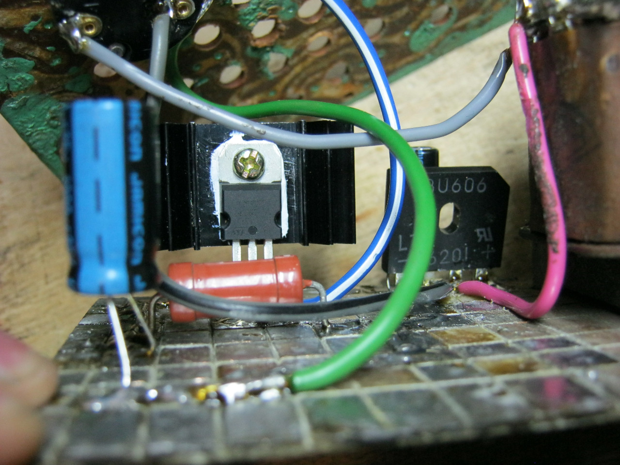
Here we see the GBU606 imported diode bridge. It is designed for current up to 6 amperes, which is more than enough for our power supply, since it will deliver a maximum of 1.5 amperes to the load. I put the LM-ku on the radiator using KPT-8 paste to improve heat transfer. Well, everything else, I think, is familiar to you.
And here is the antediluvian transformer, which gives me a voltage of 12 volts on the secondary winding.

We carefully pack all this into the case and remove the wires.

So what do you think? ;-)

The minimum voltage I got was 1.25 Volts, and the maximum voltage was 15 Volts.


I put any voltage, in this case the most common 12 Volts and 5 Volts


Everything works with a bang!
This power supply is very convenient for adjusting the speed of a mini drill, which is used for drilling boards.

Analogues on Aliexpress
By the way, on Ali you can immediately find a ready-made set of this block without a transformer.

Too lazy to collect? You can take a ready-made 5 Ampere for less than $ 2:

You can view by this link.
If 5 Amperes is not enough, then you can look at 8 Amperes. It will be enough even for the most seasoned electronics engineer:

Beginner Radio Amateur Competition
“My amateur radio design”
The design of a simple laboratory power supply on transistors from “0” to “12” volts, and a detailed description of the entire manufacturing process of the device
Competitive design of a beginner radio amateur:
“Regulated 0-12 V transistorized power supply”
Hello dear friends and visitors of the site!
I present to your court the fourth competitive work.
The author of the design Folkin Dmitry, Zaporozhye, Ukraine.
Adjustable power supply 0-12 V on transistors
I needed a PSU adjustable from 0 to ... B (the more the better). I reviewed several books and settled on the design proposed in Borisov's book "Young Radio Amateur". Everything is very well written there, just for a beginner radio amateur. In the process of creating such a complex device for me, I made some mistakes, the analysis of which I made in this material. My device consists of two parts: an electrical part and a wooden case.
Part 1. The electrical part of the PSU.
Picture 1 - Schematic diagram of the power supply from the book
I started with the selection of the necessary parts. I found some of them at home, and bought others on the radio market.
Figure 2 - Electrical Parts

On fig. 2 shows the following details:
1 - voltmeter, showing the output voltage of the PSU (I bought an unnamed voltmeter with three scales, to which a shunt resistor must be selected for correct readings);
2 - PSU power supply plug(I took a charger from Motorola, took out the board, and left the plug);
3 - light bulb with cartridge, which will serve as an indicator of the connection of the PSU to the network (12.5 V 0.068 A bulb, I found two of these in some old radio);
4 - switch from a network extension cord for a computer (there is a light bulb inside it, unfortunately, I had a burnt one);
5 - resistor 10 kOhm variable adjusting group A, i.e. with a linear functional characteristic and a handle to it; needed to smoothly change the output voltage of the PSU (I took the SP3-4am, and the handle from the radio);
6 - red "+" and black "-" terminals, serving to connect the load to the PSU;
7 - fuse 0.5 A, mounted in latches on legs (I found a 6T500 glass fuse with four legs in an old radio);
8 - step-down transformer 220 V / 12 V also on four legs (TVK-70 is possible; I had it without marking, but the seller wrote “12 V” on it);
9 - four diodes with a maximum rectified current of 0.3 A for a rectifier diode bridge (you can D226, D7 series with any letter or a KTs402 rectifier unit; I took D226B);
10 - medium or high power transistor with a radiator and a fixing flange (you can P213B or P214 - P217; I took P214 immediately with a radiator so that it does not heat up);
11 - two 500 uF electrolytic capacitors or more, one 15 V or more, the second 25 V or more (K50-6 is possible; I took K50-35 both at 1000 uF, one 16 V, the second 25 V);
12 - zener diode with a stabilization voltage of 12 V(you can D813, D811 or D814G; I took D813);
13 - low-power low-frequency transistor(you can MP39, MP40 - MP42; I have MP41A);
14 - constant resistor 510 Ohm, 0.25 W(you can MLT; I took a trimmer SP4-1 for 1 kOhm, because its resistance will need to be selected);
15 - constant resistor 1 kOhm, 0.25 W(I got a high-precision ± 1%);
16 - constant resistor 510 Ohm, 0.25 W(I have MLT)
Also for the electrical part I needed:
– one-sided foil textolite(Fig. 3);
– homemade mini drill with drills with a diameter of 1, 1.5, 2, 2.5 mm;
- wiring, bolts, nuts and other materials and tools.
Figure 3 - On the radio market I came across a very old Soviet textolite

Further, by measuring the geometric dimensions of the existing elements, I drew a future board in a program that does not require installation. Then I took up the production of a printed circuit board using the LUT method. I did it for the first time, so I used this video tutorial _http://habrahabr.ru/post/45322/.
Stages of PCB manufacturing:
1 . I printed out the drawn board in a printing house on a laser printer on glossy paper 160 g / m2 and cut it out (Fig. 4).
Figure 4 - The image of tracks and the arrangement of elements on glossy paper

2 . I cut off a piece of textolite measuring 190x90 mm. For lack of scissors for metal, I used ordinary clerical scissors, it was cut for a long time and hard. With the help of zero sanding paper and 96% ethanol, I prepared the textolite for toner transfer (Fig. 5).
Figure 5 - Prepared foil textolite

3 . First, using an iron, I transferred the toner from the paper to the metallized part of the textolite, heated it for a long time, about 10 minutes (Fig. 6). Then he remembered that he also wanted to do silk-screen printing, i.e. drawing a picture on the board from the side of the details. I attached paper with the image of the details to the non-metallized part of the textolite, heated it for a short time, about 1 minute, it turned out rather badly. Still, first it was necessary to silkscreen, and then transfer the tracks.
Figure 6 - Paper on textolite after heating with an iron

4 . Next, you need to remove this paper from the surface of the textolite. I used warm water and a shoe brush with metal bristles in the middle (Figure 7). He scrubbed the paper very hard. Perhaps it was a mistake.
Figure 7 - Brush for footwear

5 . After cleaning from glossy paper, Figure 8 shows that the toner has been transferred, but some tracks are broken. It's probably due to the hard work of the brush. Therefore, I had to buy a marker for CD / DVD discs and draw almost all the tracks and contacts manually with it (Fig. 9).
Figure 8 - Textolite after toner transfer and paper removal

Figure 9 - Paths drawn with a marker

6 . Next, you need to etch unnecessary metal from the textolite, leaving the drawn tracks. I did it this way: I poured 1 liter of warm water into a plastic bowl, poured half a jar of ferric chloride into it and stirred it with a plastic teaspoon. Then he put a foil textolite with marked paths there (Fig. 10). On a jar of ferric chloride, the promised pickling time is 40-50 minutes (Fig. 11). After waiting for the specified time, I did not find any changes on the future board. Therefore, he poured all the ferric chloride that was in the jar into the water and stirred it. During the pickling process, I stirred the solution with a plastic spoon to speed up the process. It took a long time, about 4 hours. To speed up the etching, it would be possible to heat the water, but I did not have such an opportunity. The ferric chloride solution can be repaired with iron nails. I did not have them, so I used thick bolts. Copper settled on the bolts, and a precipitate appeared in the solution. I poured the solution into a three-liter plastic bottle with a thick neck and put it in the pantry.
Figure 10 - PCB blank floats in ferric chloride solution

Figure 11 - A jar of ferric chloride (weight not specified)

7 . After etching (Fig. 12), I gently washed the board with warm soapy water and removed the toner from the tracks with ethyl alcohol (Fig. 13).
Figure 12 - Textolite with etched tracks and toner

Figure 13 - Textolite with etched tracks without toner

8 . Next, I started drilling holes. To do this, I have a homemade mini-drill (Fig. 14). To make it, I had to disassemble an old broken Canon i250 printer. From there I took a 24 V, 0.8 A motor, a power supply to it and a button. Then, on the radio market, I purchased a collet chuck for a 2 mm shaft and 2 sets of drills with a diameter of 1, 1.5, 2, 2.5 mm (Fig. 15). The cartridge is put on the motor shaft, a drill with a holder is inserted and clamped. On top of the motor, I glued and soldered a button that powers the minidrill. Drills are not particularly amenable to centering, so they “drive” a little on the sides when working, but you can use it for amateur purposes.
Figure 14 -

Figure 15 -

Figure 16 - Board with drilled holes

9 . Then I cover the board with flux, lubricating it with a thick layer of pharmacy glycerin with a brush. After that, you can tin the tracks, i.e. cover them with a layer of tin. Starting with wide tracks, I led a large drop of solder on the soldering iron along the tracks until I completely tinned the board (Fig. 17).
Figure 17 - Tinned board

10. At the end, I mounted the parts on the board. I started with the most massive transformer and radiator, and finished with transistors (I read somewhere that transistors are always soldered at the end) and connecting wires. Also at the end of the installation in the zener diode circuit break, marked in fig. 1 with a cross, I turned on the multimeter and picked up such a resistance of the SP4-1 tuning resistor so that a current of 11 mA was established in this circuit. Such adjustment is described in Borisov's book "Young Radio Amateur".
Figure 18 - Board with parts: bottom view

Figure 19 - Board with details: top view

Figure 18 shows that I didn’t guess a little with the location of the holes for mounting the transformer and radiator, I had to drill more. Also, almost all the holes for the radio components turned out to be slightly smaller in diameter, because the legs of the radio components did not fit. Perhaps the holes got smaller after solder tinning, so they should have been drilled after tinning. Separately, it must be said about the holes for the transistors - their location also turned out to be wrong. Here I had to draw the diagram more carefully and more carefully in the Sprint-Layout program. When arranging the base, emitter and collector of the P214 transistor, I should have taken into account that the radiator is installed on the board with its bottom side (Fig. 20). To solder the terminals of the P214 transistor to the desired tracks, I had to use copper pieces of wire. And the MP41A transistor had to bend the base terminal to the other side (Fig. 21).
Figure 20 - Holes for the outputs of the transistor P214

Figure 21 - Holes for the conclusions of the MP41A transistor

Part 2. Production of a wooden case PSU.
For the body I needed:
- 4 plywood boards 220x120 mm;
- 2 plywood boards 110x110 mm;
- 4 plywood pieces 10x10x110 mm;
- 4 plywood pieces 10x10x15 mm;
- nails, 4 tubes of superglue.
Case manufacturing steps:
1 . First, I sawed a large piece of plywood into boards and pieces of the required size (Fig. 22).
Figure 22 - Sawn plywood boards for the hull

2
. Then I drilled a hole for the wires on the PSU power plug using a minidrill.
3
. Then I connected the bottom and side walls of the case with nails and superglue.
4
. Next, I glued the internal wooden parts of the structure. Long racks (10x10x110 mm) are glued to the bottom and sides, holding the side walls. I glued small square pieces to the bottom, a printed circuit board will be installed and attached to them (Fig. 23). Also inside the plug and behind the case, I fixed the holders for the wires (Fig. 24).
Figure 23 - Case: front view (smudges from glue are visible)

Figure 24 - Case: side view (and here the glue makes itself felt)

5 . On the front panel of the case were taken out: a voltmeter, a light bulb, a switch, a variable resistor, two terminals. I needed to drill five round holes and one rectangular hole. It took a long time, since the necessary tools were not available and I had to use what was at hand: a mini-drill, a rectangular file, scissors, sandpaper. On fig. 25 you can see a voltmeter, to one of the contacts of which a shunt trimmer of 100 kΩ is attached. Empirically, using a 9 V battery and a multimeter, it was found that the voltmeter gives the correct readings with a shunt resistance of 60 kOhm. The light bulb socket was glued perfectly with superglue, and the switch was well fixed in the rectangular hole even without glue. The variable resistor screwed into the tree well, and the terminals were fixed on nuts and bolts. I removed the backlight bulb from the switch, so instead of three, there were two contacts on the switch.
Figure 25 - PSU internals

After fixing the board in the case, installing the necessary elements on the front panel, connecting the components with wires and attaching the front wall with superglue, I got a finished functional device (Fig. 26).
Figure 26 - Ready PSU

On fig. 26 you can see by the color that the light bulb is different, not the one that was selected initially. Indeed, when a 12.5 V light bulb rated for a current of 0.068 A was connected to the secondary winding of the transformer (as indicated in the book), it burned out after a few seconds of operation. Probably due to the high current in the secondary winding. It was necessary to find a new place to attach the light bulb. I replaced the light bulb with a whole one of the same parameters, but painted in dark blue (so as not to blind my eyes) and using wires I soldered it in parallel after the capacitor C1. Now it works for a long time, but the book indicates the voltage in that circuit is 17 V and I'm afraid I will have to look again for a new place for the light bulb. Also in fig. 26 shows that a spring is inserted into the switch from above. It is necessary for the reliable operation of the button that dangled. The variable resistor knob that changes the PSU output voltage has been shortened for better ergonomics.
When turning on the PSU, I check the readings of the voltmeter and multimeter (Fig. 27 and 28). The maximum output voltage is 11 V (1 V has gone somewhere). Then I decided to measure the maximum output current, and when the maximum limit of 500 mA was set on the multimeter, the arrow went off scale. This means that the maximum output current is slightly more than 500 mA. With smooth twisting of the variable resistor knob, the PSU output voltage also smoothly changes. But the change in voltage from zero does not start immediately, but after about 1/5 turn of the knob.
So, having spent a significant amount of time, effort and finances, I nevertheless assembled a power supply unit with an adjustable output voltage of 0 - 11 V and an output current of more than 0.5 A. If I could, then anyone else can. Good luck to all!
Figure 27 - PSU check

Figure 28 - Checking the correctness of the voltmeter readings

Figure 29 - Setting the output voltage to 5 V and checking with a test light

Dear friends and guests of the site!
Do not forget to express your opinion on the competitive works and take part in discussions on the site's forum. Thanks.
Design Applications:
(15.0 KiB, 1,657 hits)
(38.2 KiB, 1,535 hits)
(21.0 KiB, 1,043 hits)
The type of power supply, as already noted, is pulsed. Such a solution drastically reduces the weight and dimensions of the structure, but it works no worse than an ordinary network transformer, to which we are accustomed. The circuit is assembled on a powerful IR2153 driver. If the microcircuit is in a DIP package, then a diode must be installed. At the expense of the diode - pay attention, it is not ordinary, but ultrafast, since the operating frequency of the generator is tens of kilohertz and ordinary rectifier diodes will not work here.

In my case, the entire circuit was assembled on a “loose” basis, since it was assembled only to check the performance. I practically did not tune the circuit and immediately started working like a Swiss watch.
Transformer- it is advisable to take it ready-made, from a computer power supply (literally anyone will do, I took a transformer with a pigtail from an ATX 350-watt power supply). At the output of the transformer, you can use a Schottky diode rectifier (also found in computer power supplies), or any fast and ultra-fast diodes with a current of 10 Amperes or more, you can also install our KD213A.


Connect the circuit to the network through a 220 Volt 100 watt incandescent lamp, in my case, I did all the tests with a 12-220 inverter with protection against short circuit and overload, and only after fine tuning I decided to connect 220 Volts to the network.
How should the assembled circuit work?
- The keys are cold, without an output load (even with an output load of 50 watts, the keys remained ice cold).
- The microcircuit should not overheat during operation.
- Each capacitor should have a voltage of about 150 volts, although the rating of this voltage may deviate by 10-15 volts.
- The circuit must operate silently.
- The power supply resistor of the microcircuit (47k) should overheat a little during operation, an insignificant overheating of the snubber resistor (100 Ohm) is also possible.
The main problems that arise after assembly
Problem 1. We assembled the circuit, when connected, the control light that is connected to the output of the transformer flashes, and the circuit itself makes strange sounds.
Solution. Most likely there is not enough voltage to power the microcircuit, try lowering the resistance of the 47k resistor to 45, if it does not help, then to 40 and so on (in 2-3kΩ steps) until the circuit works normally.
Problem 2 We assembled the circuit, when power is applied, nothing heats up and does not explode, but the voltage and current at the output of the transformer are scanty (almost equal to zero)
Solution. Replace the 400V 1uF capacitor with a 2mH inductor.
Problem 3. One of the electrolytes gets very hot.
Solution. Most likely it is non-working, replace it with a new one and at the same time check the diode rectifier, maybe it is because of the non-working rectifier that the capacitor receives a change.
The ir2153 switching power supply can be used to power powerful, high-quality amplifiers, or it can be used as a charger for powerful lead-acid batteries, or as a power supply - everything is up to you.
The power of the unit can reach up to 400 watts, for this you will need to use a 450-watt ATX transformer and replace the electrolytic capacitors with 470 microfarads - and that's it!
In general, you can assemble a switching power supply with your own hands for only $ 10-12, and then if you take all the components from the radio store, but every radio amateur has more than half of the radio components used in the circuit.
Can a master do in construction without the presence of such an indispensable tool as a screwdriver? It will not work to carry out a full-fledged work without the use of such a tool, because you constantly need to tweak or strengthen something somewhere. Such a need in the household of a screwdriver is explained by its functionality and the ability to significantly facilitate some of the stages of construction and finishing work.
You may not know which screwdriver is better, but you will definitely appreciate all its capabilities, especially those who used to screw screws with a screwdriver. But, like any technique, a cordless screwdriver loses its former efficiency over time and no longer works with the same power as before. How to solve such a problem if it occurs? Of course, you can purchase another battery, but the cost of a new battery "bites", because the masters offer an alternative - to make a 12V power supply for a screwdriver with your own hands. This is a great way out of the situation and a great opportunity to try your hand at radio engineering.
Stages of preliminary work: getting ready for design
Before proceeding with the alteration of the battery, select another power supply unit that is suitable in size, then it must be placed in the existing case and secured. From the inside of the prepared device, everyone cleans up and measures the internal space, which is different compared to the external contents.
What you need to know before starting construction
Examine the markings or design features indicated on the body of the working tool, and, based on these indicators, determine the voltage required for power supply. In our case, it will be enough to assemble a 12V power supply for a screwdriver with your own hands. If your requirements are anything other than 12V, keep looking for an interchangeable option. Having chosen an analogue, calculate the current consumption of a screwdriver, since the manufacturer does not indicate such a parameter. To find out, you need to know the power of the device.

If you don’t have time to select a device, and the calculations take too long, take any power supply that comes across. When buying it, in addition to the current, ask about the battery capacity. To design a 12V power supply for a screwdriver with your own hands, a device with a capacity of 1.2A and charging - 2.5 will be enough. Remember, before looking for recharging, determine the following necessary parameters:
- Block sizes.
- Minimum current.
- Required voltage level.
The process of constructing a battery pack for a screwdriver
Having picked up a new device and all the details necessary for designing, you can get to work. Assembling a 12V power supply for a screwdriver with your own hands consists of the following steps:
- Having chosen the optimal power supply, check it for similarities with the declared characteristics, which will depend on which screwdriver. It is better to use a block from a computer as a basis for a new battery.
- Disassemble the screwdriver and remove the old drive. If the case is glued, gently tap along the seam with a hammer or score with a thin knife blade. This will open the box with the least damage.
- Unsolder the cord and leads from the plug and separate them from the rest of the structure.
- In the place where the battery power supply for the screwdriver used to be, place the other contents removed from the case.
- Lead the power cord through the opening in the case. Connect it to the power supply by soldering it in place.
- Use soldering to connect the output of the power supply for the computer to the battery terminals. Be sure to observe polarity.
- Connect the designed battery to the instrument and test it.
- If the dimensions of the new charger exceed the parameters of the old battery, it can be built inside the screwdriver handle.
- To limit the supply of voltage from the mains to the battery by a parallel supply output, install a diode with the required power from inside the “+” cable break between the battery socket, including the output, but with the “-” pole towards the engine.

What does this battery upgrade do?
The transformation of a power supply for a computer into a continuously working battery for a screwdriver has a number of advantages, namely:
- There is no need to worry about periodically recharging the device.
- Downtime during long periods of operation is kept to a minimum.
- The torque gets a constant value due to the constant current supply.
- Connecting a converted computer power supply for a screwdriver (12V) does not affect the technical parameters of the product, even if the device has not been used for a long period of time.
The only quality that is mentioned as a disadvantage is the presence of an electrical outlet near the work site. This problem can be easily solved by connecting an extension cord.

Materials and working tools for the modernization of a screwdriver
Remaking a computer power supply for a screwdriver is not difficult, moreover, such an activity is educational, especially for beginners in the field of radio mechanics. Having the necessary skills and all the components, in a short time you will have a transformed corded screwdriver. To carry out the work you will need:
- charger from a screwdriver;
- old factory battery;
- soft stranded electric cable;
- soldering iron and solder;
- acids;
- insulating tape;
- power supply from a computer (or other).
Transform options
You can use various power supply options to create a compact battery for trouble-free operation of the screwdriver.

Battery or power supply from computer equipment
A device that supports the charge of a PC or laptop is quite suitable for this purpose. The process of introducing a power supply into a screwdriver is as follows:
- The body of the screwdriver is completely disassembled.
- The old power supply is removed, and the wires are unsoldered.
- The wiring of the new unit is connected to the wiring of the old one, which feeds the old battery. When carrying out such an operation, it is important to observe the polarity!
- Turn on the screwdriver and check for performance. If all the wires are connected correctly, then the machine will work.
- The case of the device has a hole where the plug with a connector for recharging can be easily placed. By upgrading the screwdriver in this way, you get an improved device, which now in the process of work is also recharged like a laptop from a 220V network.
- A new power source is mounted inside the screwdriver, fixing it with glue.
- The remaining body elements are returned to their place and the product is twisted, giving it its original appearance.
That's all! Now you know how to make a cordless screwdriver from a cordless one.

Car battery as a power source
A car battery is a great option for remotely connecting a screwdriver to a network. To realize the idea, simply disconnect the clamps from the working tool and power it to the power source.
Important! The use of such a source for long-term operation of a screwdriver is highly discouraged.
Using a welding inverter to feed a screwdriver
To redo the old design, prepare a power supply circuit for a 12V screwdriver. The old design is improved to some extent by adding a secondary coil.
When compared with a computer battery, the advantage of the inverter is immediately noticeable. Due to the design features, it is immediately possible to determine the required voltage level and current strength at the output. This is the ideal method for those who live in radio technology.
Features of corded screwdrivers
It is possible to transform the device into a network device and according to another method, based on the production of a mobile station for feeding a screwdriver. An elastic wire is connected to the unit, to one of the ends of which a plug is attached. Although, in order to operate such a station, you will need to build a special power supply or connect a ready-made transformer with a rectifier.
Important! Do not forget to make sure that the characteristics of the transformer match the parameters of the tool.

If you are new to this business, then most likely it will be difficult for you to transform the coil with your own hands. Without having important skills, you can make a mistake with the number of turns, the selection of the wire diameter, therefore it is better to entrust such work to a specialist, or at least a person who understands the topic.
90% of equipment is sold with a built-in transformer. All that needs to be done is to choose the best option and design a rectifier for it. To solder the rectifier bridge, semiconductor diodes are used, selected strictly according to the parameters of the tool.
Experts recommend following certain rules to everyone who decides to reconstruct a screwdriver and design a 12V power supply for a screwdriver with their own hands. The tool upgrade instructions include the following tips:
- The corded screwdriver can be operated as long as you like and not worry about the battery running out. However, such a tool needs rest. Therefore, take five-minute breaks to avoid overheating or overloading the tool.
- When working with a screwdriver, do not forget to fasten the wire in the elbow area. So it will be more convenient to operate the device, and the cord will not interfere when screwing in the screws.
- Carry out a systematic cleaning of the power supply of the screwdriver from accumulations of dust and dirt deposits.
- The new battery is provided with grounding.
- Do not use more than one extension cord to connect to the network.
- Such a device is not recommended for use in high-altitude work (from two meters).
Now you know what power supply is needed for a 12V screwdriver, and what materials to use in order to make such a design yourself at home. There is no need to replace the old screwdriver with a new one. A radical decision should be made only if the unit is completely out of order, and a “dead” battery is not a problem for the craftsman. It is enough just to have an idea about radio engineering and arm yourself with a soldering iron. Then it will be easier to cope with the task.
