Somehow recently, on the Internet, I came across one circuit of a very simple power supply with the ability to adjust the voltage. It was possible to regulate the voltage from 1 Volt to 36 Volts, depending on the output voltage on the secondary winding of the transformer.
Take a close look at the LM317T in the circuit itself! The third leg (3) of the microcircuit clings to the capacitor C1, that is, the third leg is the INPUT, and the second leg (2) clings to the capacitor C2 and a 200 Ohm resistor and is the OUTPUT.
With the help of a transformer from a mains voltage of 220 volts, we get 25 volts, no more. Less is possible, more is not. Then we straighten the whole thing with a diode bridge and smooth out the ripples with the help of capacitor C1. All this is described in detail in the article how to get a constant voltage from an alternating voltage. And here is our most important trump card in the power supply - a highly stable voltage regulator chip LM317T. At the time of this writing, the price of this microcircuit was around 14 rubles. Even cheaper than a loaf of white bread.
Description of the microcircuit
LM317T is a voltage regulator. If the transformer produces up to 27-28 volts on the secondary winding, then we can easily regulate the voltage from 1.2 to 37 volts, but I would not raise the bar for more than 25 volts at the output of the transformer.
The microcircuit can be executed in the TO-220 package:

or in D2 Pack

It can pass a maximum current of 1.5 amps through itself, which is enough to power your electronic gadgets without a voltage drop. That is, we can give out a voltage of 36 Volts at a load current of up to 1.5 Amperes, and at the same time, our microcircuit will still give out 36 Volts as well - this, of course, is ideal. In reality, fractions of a volt will drop, which is not very critical. With a large current in the load, it is more expedient to put this microcircuit on a radiator.
In order to assemble the circuit, we will also need a 6.8 Kilo-ohm variable resistor, maybe even 10 Ki-ohm, as well as a 200 Ohm fixed resistor, preferably from 1 watt. Well, at the output we put a capacitor of 100 microfarads. Absolutely simple scheme!
Assembly in hardware
Previously, I had a very bad power supply still on transistors. I thought why not remake it? Here is the result ;-)

Here we see the GBU606 imported diode bridge. It is designed for current up to 6 amperes, which is more than enough for our power supply, since it will deliver a maximum of 1.5 amperes to the load. I put the LM-ku on the radiator using KPT-8 paste to improve heat transfer. Well, everything else, I think, is familiar to you.

And here is the antediluvian transformer, which gives me a voltage of 12 volts on the secondary winding.

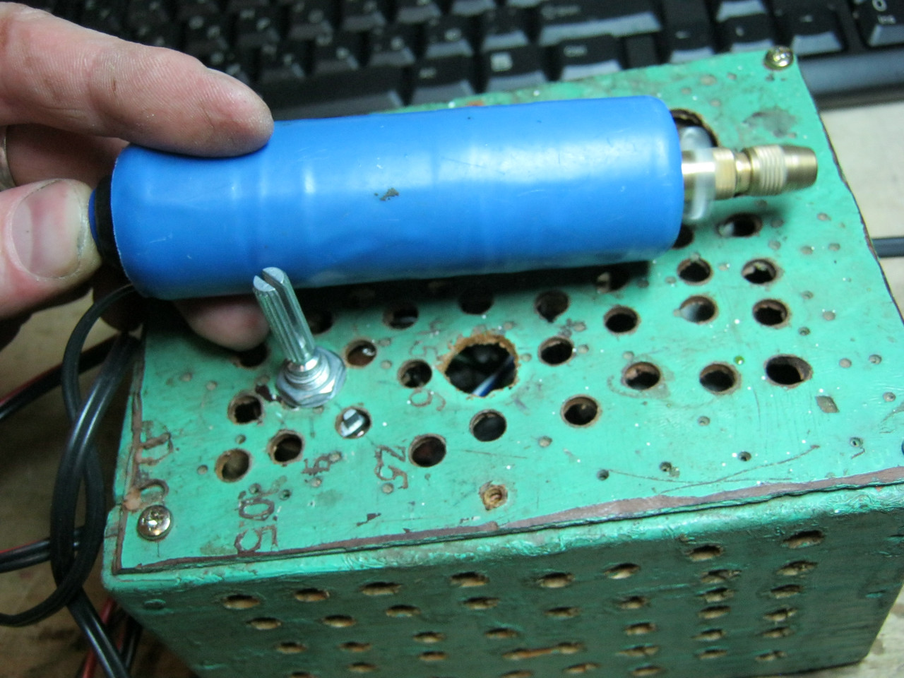
We carefully pack all this into the case and remove the wires.
So what do you think? ;-)

The minimum voltage I got was 1.25 Volts, and the maximum voltage was 15 Volts.


I put any voltage, in this case the most common 12 Volts and 5 Volts


Everything works with a bang!
This power supply is very convenient for adjusting the speed of a mini drill, which is used for drilling boards.
Analogues on Aliexpress
By the way, on Ali you can immediately find a ready-made set of this block without a transformer.

Too lazy to collect? You can take a ready-made 5 Ampere for less than $ 2:

You can view by this link.
If 5 Amperes is not enough, then you can look at 8 Amperes. It will be enough even for the most seasoned electronics engineer:

So the next device has been assembled, now the question arises from what to power it? Batteries? Batteries? Not! The power supply, we will talk about it.
Its circuit is very simple and reliable, it has short circuit protection, smooth adjustment of the output voltage.
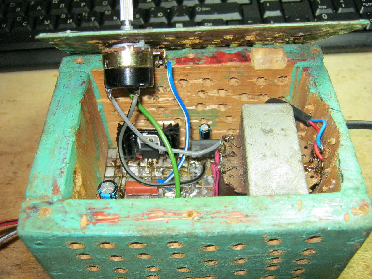
A rectifier is assembled on the diode bridge and capacitor C2, circuit C1 VD1 R3 is a reference voltage stabilizer, circuit R4 VT1 VT2 is a current amplifier for power transistor VT3, protection is assembled on transistor VT4 and R2, resistor R1 is adjusted.
I took the transformer from an old charger from a screwdriver, at the output I got 16V 2A
As for the diode bridge (at least 3 amps), I took it from the old ATX block as well as electrolytes, zener diode, resistors.
I used a zener diode at 13V, but the Soviet D814D is also suitable.
Transistors were taken from an old Soviet TV, transistors VT2, VT3 can be replaced with one composite such as KT827.
I took a nichrome wire resistor R2 with a power of 7 watts and R1 (variable), for adjustment without jumps, but in its absence you can put a regular one.
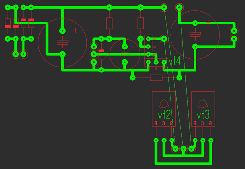
It consists of two parts: the stabilizer and protection are assembled on the first, and the power part on the second.
All parts are mounted on the main board (except for power transistors), transistors VT2 are soldered to the second board, VT3 are mounted on a radiator using thermal paste, it is unnecessary to isolate cases (collectors). Photos of the two blocks are shown below With a large 2A radiator and a small 0.6A.

Indication
Voltmeter: for it we need a 10k resistor and a 4.7k variable and I took the indicator m68501 but another one is possible. From the resistors we will assemble a divider, a 10k resistor will not allow the head to burn out, and with a 4.7k resistor we will set the maximum deviation of the arrow.
After the divider is assembled and the indication works, you need to calibrate it, for this we open the indicator and stick clean paper on the old scale and cut it out along the contour, it is most convenient to cut the paper with a blade.

When everything is glued and dry, we connect the multimeter in parallel to our indicator, and all this to the power supply, mark 0 and increase the voltage to volts, mark, etc.
Ammeter: for it we take a resistor of 0.27 ohm!!! and variable at 50k, the connection diagram is below, with a 50k resistor we set the maximum deviation of the arrow.
The graduation is the same, only the connection changes, see below, as a load, a 12 V halogen bulb is ideal.
List of radio elements
| Designation | Type | Denomination | Quantity | Note | Shop | My notepad |
|---|---|---|---|---|---|---|
| VT1 | bipolar transistor | KT315B | 1 | To notepad | ||
| VT2, VT4 | bipolar transistor | KT815B | 2 | To notepad | ||
| VT3 | bipolar transistor | KT805BM | 1 | To notepad | ||
| VD1 | zener diode | D814D | 1 | To notepad | ||
| VDS1 | Diode bridge | 1 | To notepad | |||
| C1 | 100uF 25V | 1 | To notepad | |||
| C2, C4 | electrolytic capacitor | 2200uF 25V | 2 | To notepad | ||
| R2 | Resistor | 0.45 ohm | 1 | To notepad | ||
| R3 | Resistor | 1 kOhm | 1 | To notepad | ||
| R4 | Resistor |
We all know that power supplies are an integral part of a large number of electrical appliances and lighting systems today. Without them, our life is unreal, especially since energy saving contributes to the operation of these devices. Basically, power supplies have an output voltage of 12 to 36 volts. In this article, I would like to deal with one question, is it possible to make a 12V power supply with your own hands? In principle, no problems, because this device actually has a simple design.
What can you build a power supply from?
So, what parts and devices are needed to assemble a homemade power supply? At the heart of the design are only three components:
- Transformer.
- Capacitor.
- Diodes, from which you will have to assemble a diode bridge with your own hands.
As a transformer, you will have to use a conventional step-down device that will reduce the voltage from 220 V to 12 V. Such devices are sold in stores today, you can use an old unit, you can convert, for example, a transformer with a decrease to 36 volts into a device with a decrease to 12 volt. In general, there are options, use any.
As for the capacitor, the best option for a homemade unit is a 470 microfarad capacitor with a voltage of 25V. Why with such a voltage? The thing is that the output voltage will be higher than planned, that is, more than 12 volts. And this is normal, because under load the voltage will drop to 12V.
Assembling the diode bridge
And now a very important point, which concerns the question of how to make a 12V power supply with your own hands. First, let's start with the fact that a diode is a bipolar element, like, in principle, a capacitor. That is, it has two outputs: one is a minus, the other is a plus. So, the plus on the diode is indicated by a strip, which means that without a strip it is a minus. Diode connection sequence:
- First, two elements are connected to each other according to the plus or minus scheme.
- The other two diodes are connected in the same way.
- After that, two paired structures must be connected to each other according to the plus with plus and minus with minus scheme. The main thing here is not to make a mistake.
At the end, you should get a closed structure, which is called a diode bridge. She has four connecting points: two "plus-minus", one "plus-plus" and one more "minus-minus". You can connect elements on any board of the required device. The main requirement here is a high-quality contact between the diodes.

Secondly, the diode bridge is, in fact, a conventional rectifier that rectifies the alternating current coming from the secondary winding of the transformer.
Complete instrument assembly
Everything is ready, you can proceed to the assembly of the final product of our idea. First you need to connect the transformer leads to the diode bridge. They are connected to the plus-minus connection points, the remaining points remain free.
Now you need to connect the capacitor. Please note that it also has marks that determine the polarity of the device. Only on it everything is the other way around than on diodes. That is, a negative contact is usually marked on the capacitor, which is connected to the “minus-minus” point of the diode bridge, and the opposite pole (positive) is connected to the “minus-minus” point.
It remains only to connect two power wires. For this, it is best to choose colored wires, although this is not necessary. You can use one-color ones, but on condition that they have to be marked in some way, for example, make a knot on one of them or wrap the end of the wire with electrical tape.

So, the power wires are connected. We will connect one of them to the “plus-plus” point on the diode bridge, the other to the “minus-minus” point. Everything, a 12-volt step-down power supply is ready, you can test it. In idle mode, it usually shows a voltage in the range of 16 volts. But as soon as a load is applied to it, the voltage drops to 12 volts. If there is a need to set the exact voltage, then you will have to connect a stabilizer to a home-made device. As you can see, making a power supply with your own hands is not very difficult.
Of course, this is the simplest circuit, power supplies can be with different parameters, where there are two main ones:
As an addition, a function can be used that distinguishes between regulated (pulse) and unregulated (stabilized) power supply models. The first are indicated by the ability to change the output voltage in the range from 3 to 12 volts. That is, the more complex the design, the more opportunities the units as a whole have.
![]()
And the last. Homemade power supplies are not entirely safe devices. So when testing them, it is recommended to move a certain distance and only after that to turn on the 220 volt network. If you calculated something inaccurately, for example, you chose the wrong capacitor, then there is a high probability that this element will simply explode. An electrolyte is poured into it, which, during an explosion, is sprayed over a decent distance. In addition, do not replace or solder when the power supply is on. There is a lot of voltage going on the transformer, so don't play with fire. All alterations must be carried out only with the device turned off.
Can a master do in construction without the presence of such an indispensable tool as a screwdriver? It will not work to carry out a full-fledged work without the use of such a tool, because you constantly need to tweak or strengthen something somewhere. Such a need in the household of a screwdriver is explained by its functionality and the ability to significantly facilitate some of the stages of construction and finishing work.
You may not know which screwdriver is better, but you will definitely appreciate all its capabilities, especially those who used to screw screws with a screwdriver. But, like any technique, a cordless screwdriver loses its former efficiency over time and no longer works with the same power as before. How to solve such a problem if it occurs? Of course, you can purchase another battery, but the cost of a new battery "bites", because the masters offer an alternative - to make a 12V power supply for a screwdriver with your own hands. This is a great way out of the situation and a great opportunity to try your hand at radio engineering.
Stages of preliminary work: getting ready for design
Before proceeding with the alteration of the battery, select another power supply unit that is suitable in size, then it must be placed in the existing case and secured. From the inside of the prepared device, everyone cleans up and measures the internal space, which is different compared to the external contents.
What you need to know before starting construction
Examine the markings or design features indicated on the body of the working tool, and, based on these indicators, determine the voltage required for power supply. In our case, it will be enough to assemble a 12V power supply for a screwdriver with your own hands. If your requirements are anything other than 12V, keep looking for an interchangeable option. Having chosen an analogue, calculate the current consumption of a screwdriver, since the manufacturer does not indicate such a parameter. To find out, you need to know the power of the device.

If you don’t have time to select a device, and the calculations take too long, take any power supply that comes across. When buying it, in addition to the current, ask about the battery capacity. To design a 12V power supply for a screwdriver with your own hands, a device with a capacity of 1.2A and charging - 2.5 will be enough. Remember, before looking for recharging, determine the following necessary parameters:
- Block sizes.
- Minimum current.
- Required voltage level.
The process of constructing a battery pack for a screwdriver
Having picked up a new device and all the details necessary for designing, you can get to work. Assembling a 12V power supply for a screwdriver with your own hands consists of the following steps:
- Having chosen the optimal power supply, check it for similarities with the declared characteristics, which will depend on which screwdriver. It is better to use a block from a computer as a basis for a new battery.
- Disassemble the screwdriver and remove the old drive. If the case is glued, gently tap along the seam with a hammer or score with a thin knife blade. This will open the box with the least damage.
- Unsolder the cord and leads from the plug and separate them from the rest of the structure.
- In the place where the battery power supply for the screwdriver used to be, place the other contents removed from the case.
- Lead the power cord through the opening in the housing. Connect it to the power supply by soldering it in place.
- Use soldering to connect the output of the power supply for the computer to the battery terminals. Be sure to observe polarity.
- Connect the designed battery to the instrument and test it.
- If the dimensions of the new charger exceed the parameters of the old battery, it can be built inside the screwdriver handle.
- To limit the supply of voltage from the mains to the battery by a parallel supply output, install a diode with the required power from inside the “+” cable break between the battery socket, including the output, but with the “-” pole towards the engine.

What does this battery upgrade do?
The transformation of a power supply for a computer into a continuously working battery for a screwdriver has a number of advantages, namely:
- There is no need to worry about periodically recharging the device.
- Downtime during long periods of operation is kept to a minimum.
- The torque gets a constant value due to the constant current supply.
- Connecting a converted computer power supply for a screwdriver (12V) does not affect the technical parameters of the product, even if the device has not been used for a long period of time.
The only quality that is mentioned as a disadvantage is the presence of an electrical outlet near the work site. This problem can be easily solved by connecting an extension cord.

Materials and working tools for the modernization of a screwdriver
Remaking a computer power supply for a screwdriver is not difficult, moreover, such an activity is educational, especially for beginners in the field of radio mechanics. Having the necessary skills and all the components, in a short time you will have a transformed corded screwdriver. To carry out the work you will need:
- charger from a screwdriver;
- old factory battery;
- soft stranded electric cable;
- soldering iron and solder;
- acids;
- insulating tape;
- power supply from a computer (or other).
Transform options
You can use various power supply options to create a compact battery for trouble-free operation of the screwdriver.

Battery or power supply from computer equipment
A device that supports the charge of a PC or laptop is quite suitable for this purpose. The process of introducing a power supply into a screwdriver is as follows:
- The body of the screwdriver is completely disassembled.
- The old power supply is removed, and the wires are unsoldered.
- The wiring of the new unit is connected to the wiring of the old one, which feeds the old battery. When carrying out such an operation, it is important to observe the polarity!
- Turn on the screwdriver and check for performance. If all the wires are connected correctly, then the machine will work.
- The case of the device has a hole where the plug with a connector for recharging can be easily placed. By upgrading the screwdriver in this way, you get an improved device, which now in the process of work is also recharged like a laptop from a 220V network.
- A new power source is mounted inside the screwdriver, fixing it with glue.
- The remaining body elements are returned to their place and the product is twisted, giving it its original appearance.
That's all! Now you know how to make a cordless screwdriver from a cordless one.

Car battery as a power source
A car battery is a great option for remotely connecting a screwdriver to a network. To realize the idea, simply disconnect the clamps from the working tool and power it to the power source.
Important! The use of such a source for long-term operation of a screwdriver is highly discouraged.
Using a welding inverter to feed a screwdriver
To redo the old design, prepare a power supply circuit for a 12V screwdriver. The old design is improved to some extent by adding a secondary coil.
When compared with a computer battery, the advantage of the inverter is immediately noticeable. Due to the design features, it is immediately possible to determine the required voltage level and current strength at the output. This is the ideal method for those who live in radio technology.
Features of corded screwdrivers
It is possible to transform the device into a network device and according to another method, based on the production of a mobile station for feeding a screwdriver. An elastic wire is connected to the unit, to one of the ends of which a plug is attached. Although, in order to operate such a station, you will need to build a special power supply or connect a ready-made transformer with a rectifier.
Important! Do not forget to make sure that the characteristics of the transformer match the parameters of the tool.

If you are new to this business, then most likely it will be difficult for you to transform the coil with your own hands. Without having important skills, you can make a mistake with the number of turns, the selection of the wire diameter, therefore it is better to entrust such work to a specialist, or at least a person who understands the topic.
90% of equipment is sold with a built-in transformer. All that needs to be done is to choose the best option and design a rectifier for it. To solder the rectifier bridge, semiconductor diodes are used, selected strictly according to the parameters of the tool.
Experts recommend following certain rules to everyone who decides to reconstruct a screwdriver and design a 12V power supply for a screwdriver with their own hands. The tool upgrade instructions include the following tips:
- The corded screwdriver can be operated as long as you like and not worry about the battery running out. However, such a tool needs rest. Therefore, take five-minute breaks to avoid overheating or overloading the tool.
- When working with a screwdriver, do not forget to fasten the wire in the elbow area. So it will be more convenient to operate the device, and the cord will not interfere when screwing in the screws.
- Carry out a systematic cleaning of the power supply of the screwdriver from accumulations of dust and dirt deposits.
- The new battery is provided with grounding.
- Do not use more than one extension cord to connect to the network.
- Such a device is not recommended for use in high-altitude work (from two meters).
Now you know what power supply is needed for a 12V screwdriver, and what materials to use in order to make such a design yourself at home. There is no need to replace the old screwdriver with a new one. A radical decision should be made only if the unit is completely out of order, and a “dead” battery is not a problem for the craftsman. It is enough just to have an idea about radio engineering and arm yourself with a soldering iron. Then it will be easier to cope with the task.
This powerful 12 volt power supply circuit generates a load current of up to 5 amperes. In the power supply circuit, a three-pin is used.
Brief description of Lm338:
- U input: 3 to 35 V.
- Uout: 1.2 to 32 V.
- Iout: 5 A (max)
- Working temperature: from 0 to 125 gr. C
Power supply 12V 5A on an integrated circuit LM338
The voltage from the network is supplied to the step-down transformer through the 7A fuse FU1. V1 at 240 volts, used to protect the power supply circuit from voltage surges in the mains. The transformer Tr1 is a step-down transformer with a voltage on the secondary winding of at least 15 volts with a load current of at least 5 amperes.
The reduced voltage from the secondary winding is fed to a diode bridge, consisting of four rectifier diodes VD1-VD4. An electrolytic capacitor C1 is installed at the output of the diode bridge, designed to smooth out the ripples of the rectified voltage. Diodes VD5 and VD6 are used as protection devices to prevent the discharge of capacitors C2 and C3 from a small leakage current in the LM338 regulator. Capacitor C4 is used to filter the high-frequency component of the power supply.
For the normal operation of the 12V power supply, the LM338 voltage regulator must be installed on the radiator. Instead of rectifier diodes VD1-VD4, you can use a rectifier assembly for a current of at least 5 amperes, for example, KBU810.
Power supply for 12 volts on the stabilizer 7812
The following circuit of a powerful power supply for 12 volts and 5 amperes of load is built on an integrated 7812. Since the permissible maximum load current of this stabilizer is limited to 1.5 amperes, a power transistor VT1 is added to the power supply circuit. This transistor is known as the bypass external transistor.

If the load current is less than 600 mA, then it will flow through the 7812 stabilizer. If the current exceeds 600 mA, then the resistor R1 will have a voltage of more than 0.6 volts, as a result of which the power transistor VT1 begins to conduct additional current through itself to the load. Resistor R2 limits excessive base current.
The power transistor in this circuit must be placed on a good radiator. The minimum input voltage must be a few volts higher than the output voltage of the regulator. Resistor R1 should be rated at 7 watts. Resistor R2 can have a power of 0.5 watts.
