Power supply for a cordless screwdriver from a 220 volt network
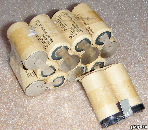
A screwdriver is a very useful tool, it can be used to drill, twist and even cut threads. All screwdrivers that I saw were cordless, which gave great autonomy, you can work where there is no outlet. Usually, two batteries of nickel-cadmium batteries are included in the kit. But their resource is relatively short and after a year the capacity drops dramatically due to damage to individual cans.
Batteries have to be charged constantly, every time before work, and they only last for half an hour or less. Therefore, I decided to assemble a power supply unit for a screwdriver from a 220 volt outlet.

An electronic ballast for 160W halogens was chosen as the basis of the power supply. It is a half-bridge oscillator based on two MJE13009 transistors.
This power supply has current feedback, for this reason it will at least not start without load. Taking into account this fact, a 15W incandescent lamp was connected in parallel with the output. Its function is to recognize the minimum load for the PSU and illuminate the drilling work area.
The problem of starting an electronic transformer can also be solved by changing the feedback of the oscillator from current to voltage feedback. To do this, it is taken not from a small ring, but from an output transformer. But in this case, the priority was the ease of rework.

The power supply board is located in the battery case. Its voltage is 16.8 volts. The battery capacity is 1200mA/H.
The output transformer is toroidal, made on a ring magnetic core. Initially, the secondary winding was wound with a "litz wire" of several wires in heat shrink and contained 8 turns. The new winding was wound with thick wire, 2 x 12 turns, to give a midpoint. The transformer leads are connected to an assembly of two Schottky diodes from a computer power supply (in the photo it is on a radiator). The output of the rectifier is connected to the inductor on the ring, from the computer motherboard. The electrolytic capacitor at the output has a capacitance of 4700uF, it is shunted by a 0.1uF ceramic capacitor. To remove the ripple with the mains frequency after the rectifier at the input of the electronic ballast, an electrolytic capacitor with a capacity of 220 microfarads is added.

Added elements are shown in green on the diagram.

The described refinement of the screwdriver made it possible to feed it directly from the 220 volt network. A thermistor with a resistance of 7 ohms is installed in the break of the 220 Volt power circuit, which smooths out the current surge at the moment of switching on.

This article was written for
